Electric Motorcycle
Summary
The full documentation for this project, in PDF format (as submitted at the end of the capstone) is available on GitHub.
- Programmed and assembled a fully electric dirt-bike from scratch.
- Assembled using an Arduino Mega for control with C++, a touchscreen display, custom aluminum panels, isolated inputs and outputs, and all-custom power distribution and analog sensing, mounted on a stripped frame.
- This project was my capstone for Electronics Engineering Technology.
- Features fully-fleshed out faults, including current, voltage, range, charging, and temperature faults.
- A fully-custom, hand-wired analog amplifier stack for telemetry. PCBs were designed and assembled by hand.
- A fully-custom, switching charging circuit. (note: I only had a 4S charger and this system runs at 16S, so a switching relay circuit changes the cell layout with the press of a button!)
- Safety features for over-current, over-voltage, over-temperature, and under-voltage. I also included a kill switch and brake light. A fallback control system was implemented, so if the Arduino or related control systems fail, the bike will still run.
- The killswitch was hard-wired to the main control relay, so if the switch is thrown, the bike will not run, no matter what.
- A Nextion touchscreen display with speed, telemetry, range estimation, faults, and all the normal indicators you would get on a motorcycle!
- Every single system on this bike was built by hand, from the ground-up!
- Range predictions can be made based on the remaining charge and the current session’s usage history!
- Communication between the Arduino and the display is done over UART.
- RJ45 connectors are used for all data connections.
The Panels
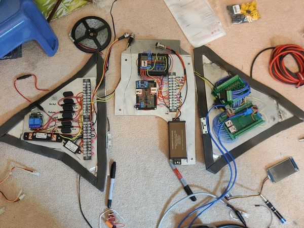
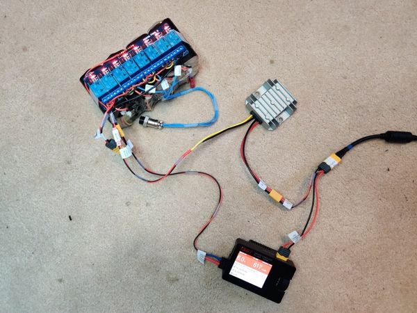
The panels were the heart of the entire machine. Here they are laid out on the ground, in all their glory. On the left is the power distrobution panel, the middle is the general-purpose board for analog sensing and connections, and the right is the controller panel.
The Controller
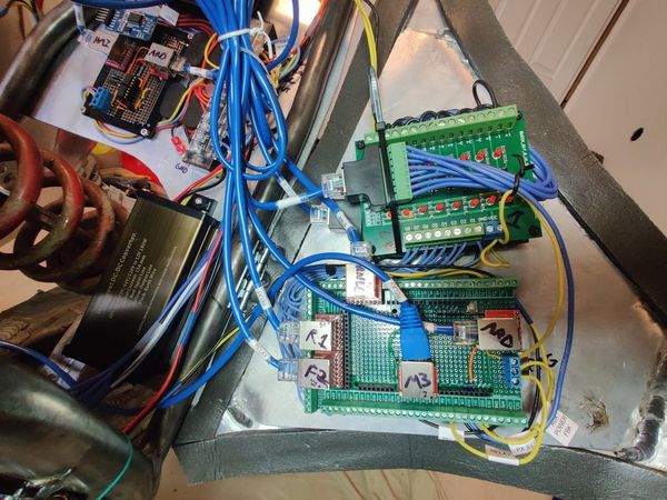
The main controller was an Arduino Mega, which was chosen for its large number of I/O pins and simplicity. All digital IO within the 5V system is isolated using optocouplers, and all analog IO is isolated using a custom amplifier stack. RJ45 was used to connect all digital systems.
Power Distribution
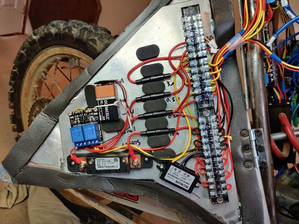
The power distrobution panel includes fused outputs for each discrete 5/12V system on the vehicle. The 9V battery provided a negative rail for the analog stack. The relay pack was to allow the controller to toggle power to the 12V system, and the negative rail to the analog stack. The bottom left is a current shunt, for sensing ambient draw for the entire control system. Bottom right is the 12V->5V buck converter, which powers the Arduino and the display.
Center Panel
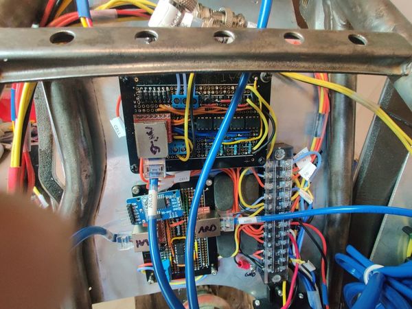
The center panel served as both a housing for misc electrical components, and the center connecting point for the other two panels. It had a real-time clock on it, and the stack of OPAMPS used for preprocessing of signals from sensors all over the vehicle, before being sent to the Arduino.
The Screen
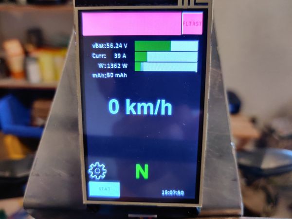
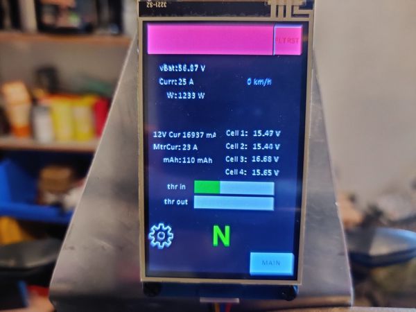
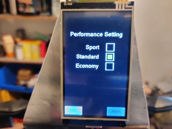
There was a Nextion 3.5" screen at the front of the bike, which was used to display all the information to the rider. It was connected to the Arduino over UART, and was powered by the 5V rail. It was touchscreen using a resistive sensor, and had a custom GUI built for it. There were screens for the main display, the settings, and the faults. The main display had two windows, one was simple with a large font, and one was verbose with a smaller font.
The Battery
The battery was designed using recycled 4S2P Li-Ion packs from a mall in Toronto. Each pack had an integrated BMS, which were not the best by a long shot, but this machine was built on a budget. Since I only had a 1-6S smart charger, I used relays to change the battery configuration between 4S and 16S.
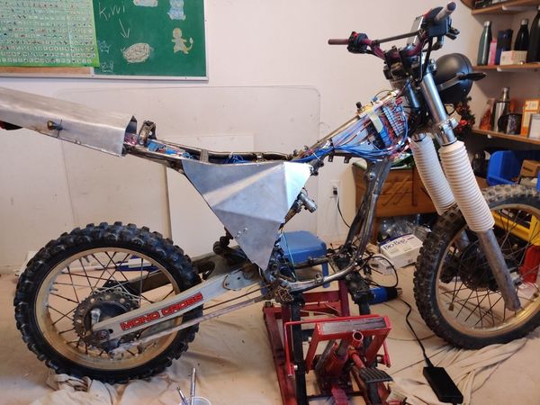
The Aesthetics
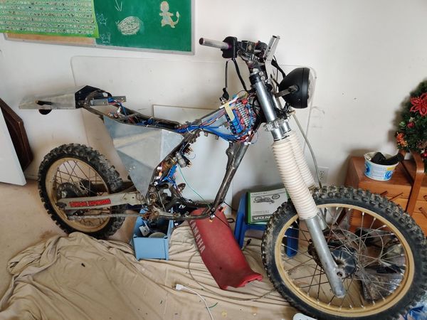
The bike was built on a budget, so the aesthetics were not the best. It started on a YZ125 frame from the 80s, upon which I mounted custom-made aluminum panels, specifically designed to resemble the Tesla CyberTruck. The panels were cut using a cutoff wheel, and bent using a 50-ton press. The convex insides of the panels were not suitable to mount electronics to, so flat mounting plates were cut to the shape of the panel edges, and TIG welded on. M3 mounting holes were drilled and tapped wherever needed. The sensor mounts were not pretty, as they were all either bolted-on shunts for current, or welded mounts for inductive proximity sensors for speed sensing, but they were all fully functional, which was all that mattered to me at the time.
The Motor
It does not take much to notice the motor is missing! This was a supplier issue. I ordered a 25kW motor and controller from a supplier in the UK, but they went out of business during the early pandemic before they were able to assemble and ship my motor. Seen near the bottom of the front of the frame is a brushless plane motor and ESC, which was used to demonstrate the functionality of the system. Since logically it is the same as the real motor, it was a drop-in replacement for the real motor for testing purposes. This missing motor was the reason this project was scrapped after I submitted my final capstone report, and rebuilt the whole system into an electric longboard!
Project link: https://github.com/colefuerth/ElectricMotorcycle